Making a Netduino GO! Module – Conclusion
Making the OutputExpander module has been an interesting journey. The original drawings started in August 2012 and then sat on the hard drive for about eight months. Much of the time following the original drawings were spent working out how the STM8S worked. You can find out more in The Way of the Register series (something I will pick up again soon, to my mind there are a few missing topics).
For those who do not know, I’m a software engineer and electronics is a hobby. The prospect of designing a board and using SMD components would have been unthinkable to me two years ago. Today I sit here with my first prototype PCB connected to a commercial board and the output looks reasonably professional – well I’ll let you decide.
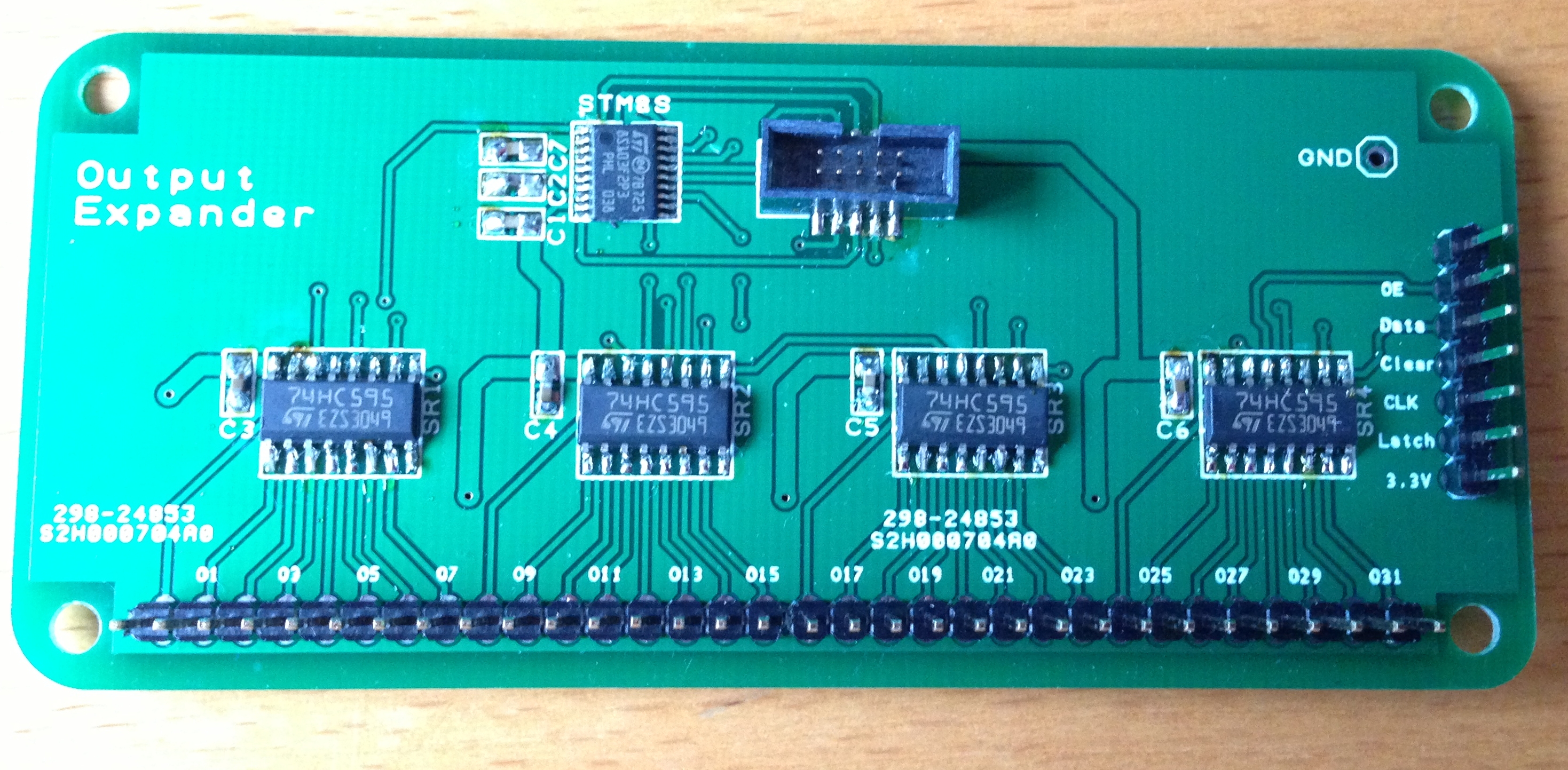
Completed Board
Not looking too bad if I say so myself.
So let’s look at what I have learned and also how long the project took.
Lessons Learned
With all projects we should look back and learn from the experience, both good and bad. So here are a few things I have learned over the past few months.
Designing the Board
The original design started life in August 2012. I probably should have taken the plunge and developed the board a little quicker than I did although in truth, I did not get the major requirement of the board, namely GoBus 1.0 really sorted out until late November 2012.
Prototyping
This was probably the simplest bit of the project. I have all of the standard components in my toolbox already and I also have the tools required. This was really a case of getting the system working. The hardest part was getting to grips with the STM8S, a story I have documented in The Way of The Register series of posts.
Schematic
During this part of the design phase I tried several different packages. All of them had strengths and weaknesses. I finally settled on DesignSpark. For me this package had three major strengths:
- It’s free
In fairness it does have a few weaknesses. The most obvious for me was the lack of the ability to add images of any kind to the design. Come on, at version 5 you should have this one!
Nets – I discovered these when producing the final draft of the schematic. These allowed the separation of the nets into logical groups/functions/areas. It made the schematic a lot cleaner.
Schematic to Manufacture
For me this was the where I learned the most. The first thing I learned was that auto-routers are dreadful. They are slow and produce some interesting board layouts. This board is a simple board and yet the auto-router still took a long time to make a half-hearted attempt at routing the board. In the end I did this manually. This was not too much of a problem as the board was simple.
Next, you have to learn to think in three dimensions. You have two layers so use them.
The Netduino modules produced by Secret Labs have nice rounded corners – these are a devil to produce in DesignSpark. I think that the module I produced has one corner which is slightly different from the others.
The cost of prototyping is a lot lower than I thought. Ten boards including shipping costs about £18 and only took 10 days.
I now know what 0403 means. The ‘0’ stands for Ohhh my goodness that’s small. Seriously, the four digits should be split into two and thy give the dimensions of the component. So for a metric component an 0403 part is 0.4 x 0.3 mm – that’s small.
The STM8S part selected has a 0.65mm pitch for the pins. I originally found this a little worrying. Don’t be afraid – they are not that bad.
Get a USB microscope when soldering SMD components. This tools is cheap and allows the examination of joints for shorts. The quality will never be great, mine only runs at 640×480, but a 400x zoom means you can be sure that you have no problems.
Add test points. There came a point when I was making the board and I needed to see the data going through to the 74HC595’s. I did not have a suitable connection and so I had to solder a piece of wire to the board:
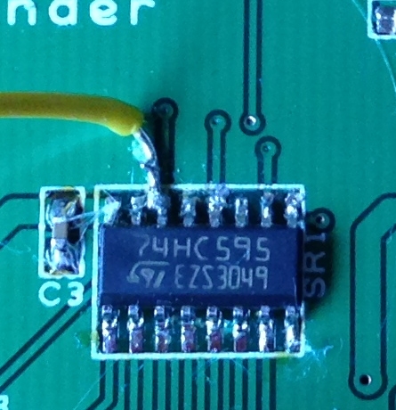
Improvised Test Point
A good test point would have made this easier.
How Long Did it Take
The original drawing started in August 2012 and the final board was put together and tested only yesterday. So in elapsed time that’s about nine months. In real working time this broke down as follows:
| Activity | Duration (Hours) |
| Building Prototype circuit | 2 |
| Prototype software | 3 |
| Schematic | 6 |
| PCB layout | 20 |
| Assembly and testing | 5 |
| Enhanced software | 4 |
| Total | 40 |
Something to bear in mind is that no production evaluation or component selection has been conducted as part of this project. It was supposed to be the final item on the list. I am still not sure if this should be taken through to manufacture – time will tell.
Another item to be considered is to achieve the Netduino GO! logo approval. At the time of writing this required the approval of the board by Secret Labs – this activity has not been completed.
Conclusion
Well, that was a hectic few weeks.
Did I enjoy it – YES!
Would I recommend that you try it – YES!
As for me, I’ll be taking a few days off of hardware development and blogging. Love doing it but it can take it’s toll.
I suppose you may be interested in some downloads…
If you use any of the code or techniques discussed in this series of posts then please let me know as I’m interested in what other people are doing with this work.
Tags: Electronics, Netduino, STM8
Tuesday, May 7th, 2013 at 6:46 pm • Electronics, Netduino, Software Development, STM8 • RSS 2.0 feed Both comments and pings are currently closed.
