Projects for 2016
Sunday, January 31st, 2016The Christmas break always gives time to plan the coming years projects. Like all hobbyists I’m sure that I’m going to be planning far more projects than I have time to complete. One thing that I am going to try and do is complete some of the projects from former years.
LED Cube
So let’s start with the LED cube. This project started a while ago and the electronics and software worked well but the LEDs have ended up sitting on a shelf for a few years. The aim was to house the cube in a suitable case but for some reason this was never really completed.
Time for a change.
The first step in the completing the project is to connect the LED cube to a base board. The board would provide the power to the LEDs, nothing more, just power to the LEDs. The design utilised a simple transistor circuit to turn the LEDs on or off. A pull-down resistor ensures that the default situation for the switch will be the off position:
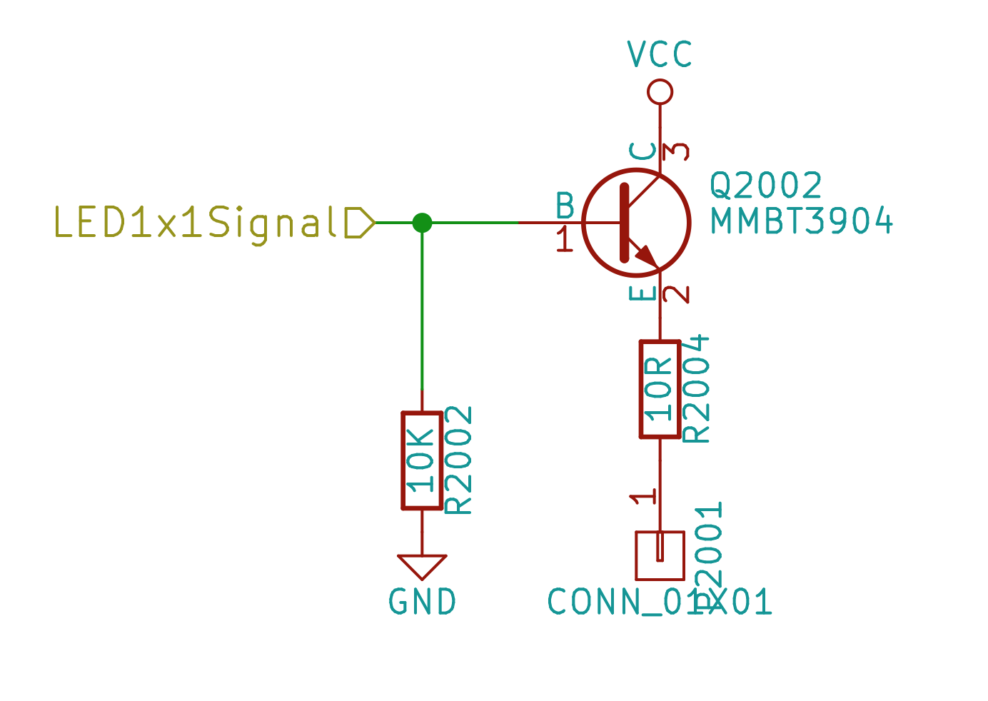
Transistor LED Schematic
Multiply this by 64 and you have the base board for the LED cube. The PCB layout looks like this:
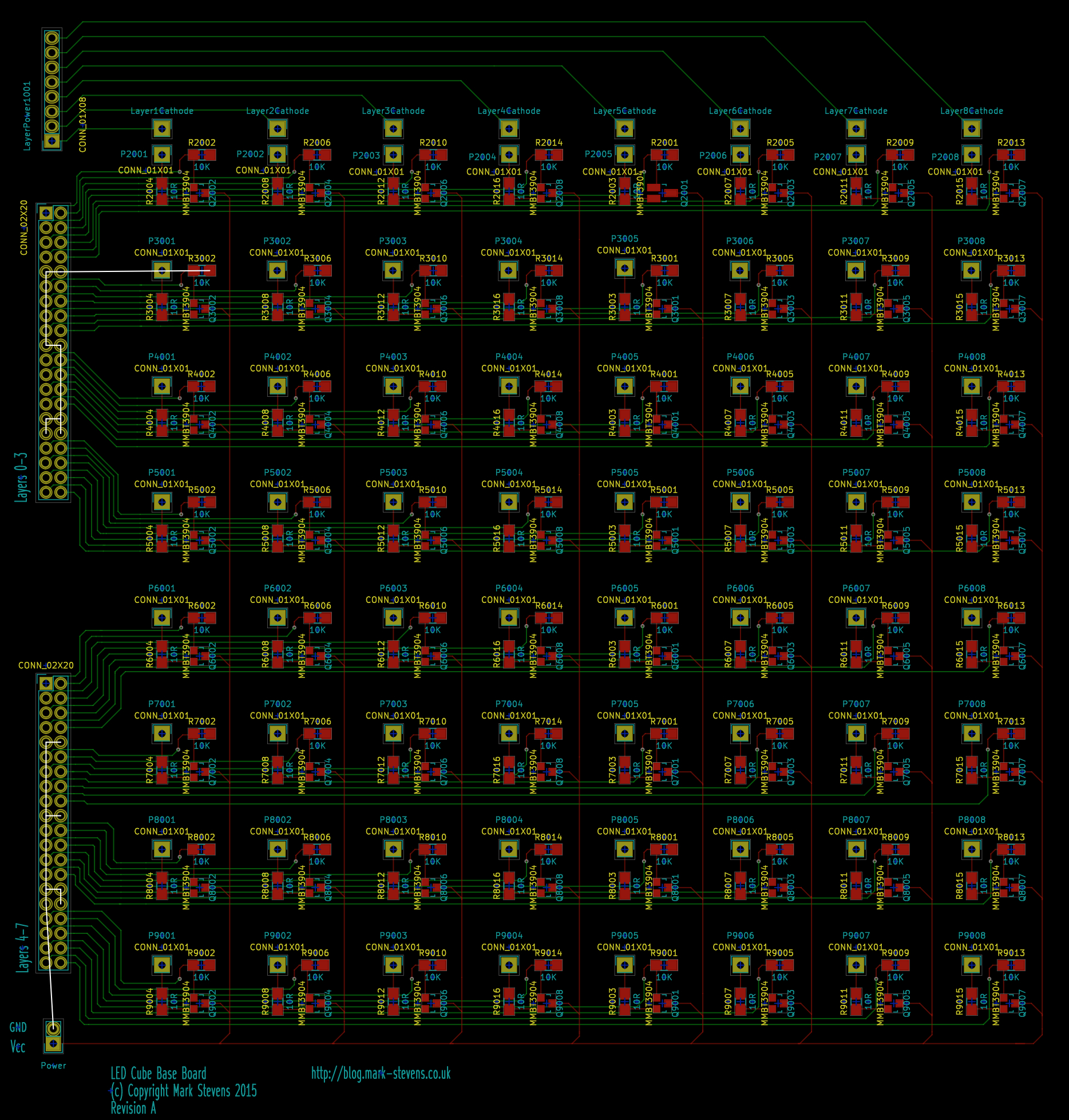
LED Cube Base Board Layout
The board design was sent for manufacture in early-mid December. This is by far the largest (although not the most complex) design I have had made. The board was 20cm x 20cm. The final boards arrived just before Christmas:
The top of the board has 64 pads laid out in a grid for the LEDs:

The bottom of the board has 64 copies of the power circuit above:

LED Base Board Power Circuit
When I was applying the solder paste to this board I was wishing I could afford a solder mask. After building a couple of power circuits it occurred to me that a simple mask could be made using an overhead acetate (remember these from the 1980s/90s) and a dremel. It does not matter that the holes in the mask would be circular, only that they are in the correct position. A 1mm diameter drill bit in a dremel and a piece of acetate provide the right amount of solder paste to the board.
A tip for the future.
The next step was to mouth the LEDs. Easier said than done. The cube had already been assembled and so the legs of the LEDs had to be coaxed into position. Several hours later we have:
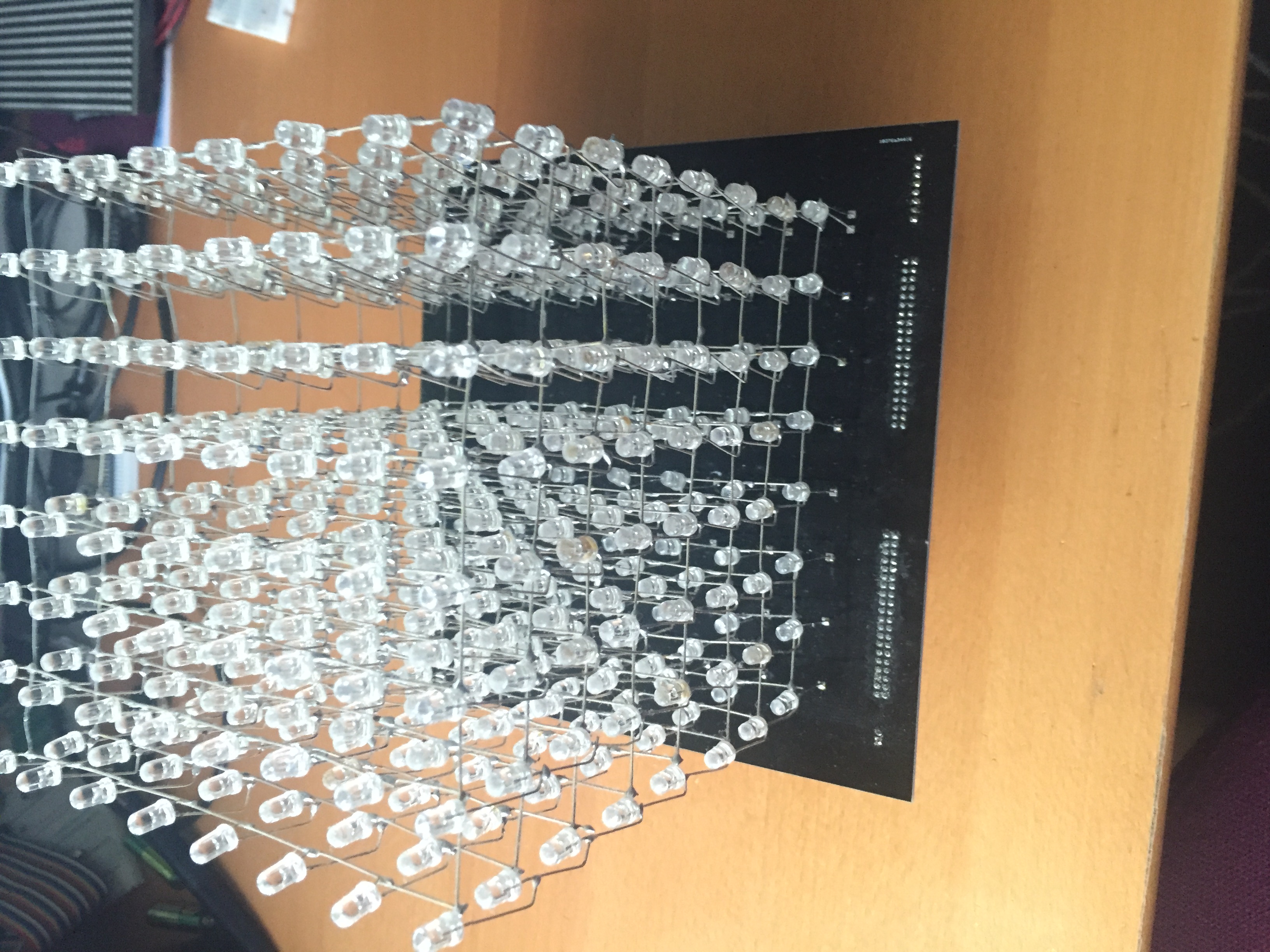
LEDs On Base Board
Soldering on some connectors allows a quick check of each LED in the cube. It works 🙂
Next step is to look at the control circuitry.
Other Plans
As well as completing the cube, there are a few other projects that are in the pipeline:
- Christmas jumper for a friend – adding some lights, we all love LEDs
- Get to grips with FPGAs
- Docker and Vagrant – I know Vagrant can help me with ESP8266 development
- ESP8266, ESP32?, Photon, Oak and RedBear Duo – There is going to be a lot of IoT in 2016
- Complete the wireless infra-red remote control
2016 – time to complete some projects and start some new ones.