Timer 1 Counting Modes
In this article we will continue to look at Timer 1, specifically:
- counting modes
- repetition counter
- update/overflow events
This article will assume some knowledge from the following two posts published previously:
Unlike previous posts we will not be resetting the system clock but will instead leave this running using the default 2 MHz internal HSI oscillator.
Test Environment
In order to demonstrate the features of the timer I will be using my Saleae Logic Analyser as we will be observing events which occur many times a second. I have the following connections set up:
| Saleae | STM8S Pin | Description |
| Ground | N/A | Ground |
| Black | PD5 | Indicate the state of the Timer 2 overflow interrupt |
| Brown | Timer 1, Channel 4 | PWM signal from Timer 1 |
| Red | PD4 | Indicate state of Timer 1 (running or halted) |
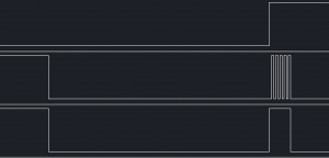
This set up will result in a series of charts from the Logic software which look like this:
The top portion of the display (labelled TIM2 Overflow) indicates when an overflow event has occurred on Timer 2. This timer is used to control the application. A change from low to high starts Timer 1 and the timer window for the observation runs to the next transition from high back to low. There is then a pause and then the whole cycle starts again.
The centre portion (labelled TIM1 PWM) shows the PWM output of Timer 1, channel 4. This is used to demonstrate what happens as we change the various values in the timer registers.
The lower portion (labelled TIM1 Overflow) shows when the Timer 1 overflow event occurs.
One thing that you can do to make the capture of these traces easier is to set a sample trigger on one of the traces. If you look at the trace labelled TIM2 Overflow you will see that one of the four square buttons is highlighted. This is showing that capture of data will begin when the logic analyser detects a signal which changes from low to high. You can make use of this by deploying and starting the application as follows:
- Compile and deploy the application
- Start data capture on the logic analyser
- Start the application
When you click the Start button on the logic analyser (step 2) a window will appear which indicates that the software is monitoring the data looking for a trigger (in this case rising edge on PD5) before it will start to capture data.
The Registers
The example code we will use shows how we can change the properties of the output and also the frequency of the interrupts generated by using the following registers:
- TIM1_CR1_DIR – Counter Direction
- TIM1_RCR – Repetition Counter
TIM1_CR1_DIR – Counter Direction
This register determines the direction of the counter, either up from 0 to the auto-reload values (set to 0) or down from the auto-reload value (set to 1).
TIM1_RCR – Repetition Counter
This counter can be used to determine the frequency of the overflow interrupts. Normally (i.e. by setting this register to 0) an overflow/underflow interrupt is generated every time the counter is reloaded from the auto-reload registers. By setting this register to any number other than zero (i.e. n), the overflow/underflow interrupt will only be generated after n + 1 overflow/underflows have been detected.
Software
We will use the registers described above to generate a series of 5 pulses every 50 mS. The code to do this is as follows:
#if defined DISCOVERY
    #include <iostm8S105c6.h>
#elif defined PROTOMODULE
    #include <iostm8s103k3.h>
#else
    #include <iostm8s103f3.h>
#endif
#include <intrinsics.h>

//--------------------------------------------------------------------------------
//
//  Timer 2 Overflow handler.
//
#pragma vector = TIM2_OVR_UIF_vector
__interrupt void TIM2_UPD_OVF_IRQHandler(void)
{
    if (PD_ODR_ODR5 == 1)
    {
        TIM1_CR1_CEN = 0;
        PD_ODR_ODR5 = 0;
        PD_ODR_ODR4 = 0;
    }
    else
    {
        //
        //  Force Timer 1 to update without generating an interrupt.
        //  This is necessary to makes sure we start off with the correct
        //  number of PWM pulses for the first instance only.
        //
        TIM1_CR1_URS = 1;
        TIM1_EGR_UG = 1;
        //
        //  Reset the indicators.
        //
        PD_ODR_ODR5 = 1;
        PD_ODR_ODR4 = 1;
        //
        //  Enable Timer 1
        //
        TIM1_CR1_CEN = 1;           //  Start Timer 1.
    }
    TIM2_SR1_UIF = 0;               //  Reset the interrupt otherwise it will fire again straight away.
}

//--------------------------------------------------------------------------------
//
//  Timer 1 Overflow handler.
//
#pragma vector = TIM1_OVR_UIF_vector
__interrupt void TIM1_UPD_OVF_IRQHandler(void)
{
    PD_ODR_ODR4 = !PD_ODR_ODR4; //0;                //  Signal to the user that Timer 1 has stopped.
    TIM1_CR1_CEN = 0;               //  Stop Timer 1.
    TIM1_SR1_UIF = 0;               //  Reset the interrupt otherwise it will fire again straight away.
}

//--------------------------------------------------------------------------------
//
//  Set up Timer 1, channel 3 to output a single pulse lasting 240 uS.
//
void SetupTimer1()
{
    TIM1_ARRH = 0x03;       //  Reload counter = 960
    TIM1_ARRL = 0xc0;
    TIM1_PSCRH = 0;         //  Prescalar = 0 (i.e. 1)
    TIM1_PSCRL = 0;
    //
    //  Select 0 for up counting or 1 for down counting.
    //
    TIM1_CR1_DIR = 0;       //  Up counter.
    //
    //  Select 0 for edge aligned, 1 for mode 1 centre aligned,
    //  2 for mode 2 centre aligned or 3 for mode 3 centre aligned.
    //
    TIM1_CR1_CMS = 0;       //  Edge aligned counter.
    //
    //  Set the following depending upon the number of PWM pulses, note
    //  n + 1 pulses will be generated before the interrupt.
    //
    TIM1_RCR = 4;           //  Repetition count.
    //
    //  Now configure Timer 1, channel 4.
    //
    TIM1_CCMR4_OC4M = 7;    //  Set up to use PWM mode 2.
    TIM1_CCER2_CC4E = 1;    //  Output is enabled.
    TIM1_CCER2_CC4P = 0;    //  Active is defined as high.
    TIM1_CCR4H = 0x01;      //  480 = 50% duty cycle (based on TIM1_ARR).
    TIM1_CCR4L = 0xe0;
    TIM1_BKR_MOE = 1;       //  Enable the main output.
    TIM1_IER_UIE = 1;       //  Turn interrupts on.
}

//--------------------------------------------------------------------------------
//
//  Setup Timer 2 to generate a 40 Hz interrupt based upon a 2 MHz timer.  This
//	will result in a signal with a frequency of 20Hz.
//
void SetupTimer2()
{
    TIM2_PSCR = 0x00;       //  Prescaler = 1.
    TIM2_ARRH = 0xc3;       //  High byte of 50,000.
    TIM2_ARRL = 0x50;       //  Low byte of 50,000.
    TIM2_IER_UIE = 1;       //  Enable the update interrupts.
    TIM2_CR1_CEN = 1;       //  Finally enable the timer.
}

//--------------------------------------------------------------------------------
//
//  Now set up the output ports.
//
//  Setup the port used to signal to the outside world that a timer event has
//  been generated.
//
void SetupOutputPorts()
{
    PD_ODR = 0;             //  All pins are turned off.
    //
    //  PD5 is used to indicate the firing of the update/overflow event for Timer 2
    //
    PD_DDR_DDR5 = 1;
    PD_CR1_C15 = 1;
    PD_CR2_C25 = 1;
    //
    //  PD4 is used to indicate the firing of the update/overflow event for Timer 1
    //
    PD_DDR_DDR4 = 1;
    PD_CR1_C14 = 1;
    PD_CR2_C24 = 1;
}

//--------------------------------------------------------------------------------
//
//  Main program loop.
//
void main()
{
    __disable_interrupt();
    SetupTimer1();
    SetupTimer2();
    SetupOutputPorts();
    __enable_interrupt();
    while (1)
    {
        __wait_for_interrupt();
    }
}
If we now have a look at the output on the Logic Analyser we can see how the various signals indicate what is happening with the Timers.
The top trace of the output shows us when Timer 2 has overflowed (i.e. every 25mS). The code above goes through a cycle of enabling Timer 1 and 25mS later disabling Timer 1. You can see the output from Timer 1, Channel 3 in the middle of the three traces. The final (bottom) trace shows when Timer 1 overflows.
We have used much of the code presented above in previous examples in the series. We are setting up the two timers (Timer 1 and Timer 2, Channel 3) and adding interrupt handlers for the counter overflows. We are also setting up Port D as an output port to give us some diagnostic traces.
One difference from previous examples is that we are running this code at a slower clock frequency. By not setting up the system clock we are running at the default clock rate (2 MHz clock from the internal clock source).
Timer 1 Overflow Handler
This handler is really simple and does nothing more than use PD4 to indicate it has been called and then turns the timer off.
Timer 2 Overflow Handler
This handler is a little more complex. The first things to note is that it uses PD5 and works out if we are starting timers or pausing (PD5 = 1).
The next thing to note is the use of two more registers TIM1_CR1_URS and TIM1_EGR_UG. These two registers are used together to force the counter register to be reloaded without generating an interrupt. This is necessary to ensure that we start from a known value.
Conclusion
We have seen how we can use the logic analyser and some output pins (PD4 and PD5) to give us information about the sequence of events (interrupts). This is a very useful diagnostic tool and often the only one which is available to you when operating in this sort of environment.
I would also suggest trying some of the following and viewing the output on a logic analyser:
- Changing the counting mode
- Removing the update of TIM1_CR1_URS and/or TIM1_EGR_UG
As always, the source code is available for download.
Source Code Compatibility
| System | Compatible? |
| STM8S103F3 (Breadboard) | |
| Variable Lab Protomodule | |
| STM8S Discovery |
Tags: Electronics, STM8
Friday, September 14th, 2012 at 1:36 pm • Electronics, STM8 • RSS 2.0 feed Both comments and pings are currently closed.


