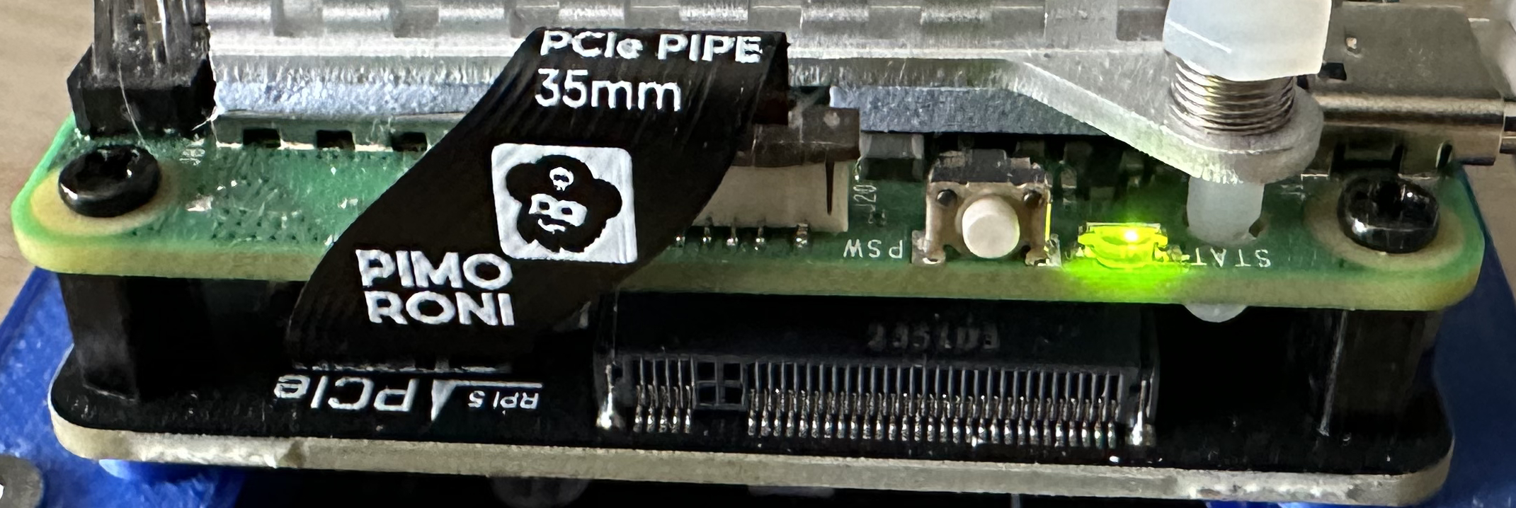
This latest chapter in the Repeatable Deployments series looks at automating the steps discussed in the Raspberry Pi and NVMe Base post. The previous post investigated the manual steps necessary to add a PCIe drive, here we will look at automating the setup process.
TL;DR The scripts and instructions for running them can be found in the AnsibleNVMe GitHub repository with the code for this article available tagged as Repeatable Deployments 3.
Automation Options
The two main (obvious) options for automation in this case would be:
In this post we will look at using Ansible as it allows remote installation and configuration without having to install scripts on the target machine.
The Hardware
The installation hardware will be based around the Raspberry Pi 5 as the PCIe bus is required for the NVMe base and associated SSD:
- Raspberry Pi (3, 4 or 5)
- 256 GByte SATA SSD
- SATA to USB adapter
- Cooling fan (for the Raspberry Pi 5)
- NVMe Base and 500GByte M2 drive
- Power Supply
- Ethernet cable
- 3D printed mounts to bring everything together
For the purpose of this post we will be configuring the system with the following credentials:
- Hostname: TestServer500
- User: clusteruser
The password will be stored in an environment variable and on a Mac this is setup by executing the following command:
export CLUSTER_PASSWORD=your-password
The remainder of this post will assume the above names and credentials but feel free to change these as desired.
Step 1 – Install the Base Operating System
The operating system is installed following the same method as described in part 1 of this series. Simply ensure that the hostname, user name and password parameters are set to those noted above (or with your substitutions).
Step 2 – Ensure SSH Works
The next thing we need to do is to check that the Raspberry Pi boots and that we can log into the system. So apply power to the board and wait for the board to boot. This normally takes a minute or two as the system will boot initially and then expand the file system before booting two more times.
Time for the first log on to the Raspberry Pi with the command:
ssh testserver500.local
If this is the first time this device has been setup with the server name then you will be asked to accept the certificates for the host along with the password for the Raspberry Pi.
The authenticity of host 'testserver500.local (fe80::67b6:b7f4:b285:2599%en17)' can't be established.
ED25519 key fingerprint is SHA256:gfttQ9vr7CeWfjyPLUdf5h2Satxr/pRrP2EjbmW2BKA.
This key is not known by any other names.
Are you sure you want to continue connecting (yes/no/[fingerprint])? yes
Warning: Permanently added 'testserver500.local' (ED25519) to the list of known hosts.
clusteruser@testserver500.local's password:
Linux TestServer500 6.6.20+rpt-rpi-2712 #1 SMP PREEMPT Debian 1:6.6.20-1+rpt1 (2024-03-07) aarch64

The programs included with the Debian GNU/Linux system are free software;
the exact distribution terms for each program are described in the
individual files in /usr/share/doc/*/copyright.

Debian GNU/Linux comes with ABSOLUTELY NO WARRANTY, to the extent
permitted by applicable law.
clusteruser@TestServer500:~ $
Answer yes to accept the certificates and then enter the password at the following prompt.
If the machine name has been used before, or if you are trying repeat deployments then you will receive a message about certificate errors:
@@@@@@@@@@@@@@@@@@@@@@@@@@@@@@@@@@@@@@@@@@@@@@@@@@@@@@@@@@@
@    WARNING: REMOTE HOST IDENTIFICATION HAS CHANGED!     @
@@@@@@@@@@@@@@@@@@@@@@@@@@@@@@@@@@@@@@@@@@@@@@@@@@@@@@@@@@@
IT IS POSSIBLE THAT SOMEONE IS DOING SOMETHING NASTY!
Someone could be eavesdropping on you right now (man-in-the-middle attack)!
It is also possible that a host key has just been changed.
The fingerprint for the ED25519 key sent by the remote host is
SHA256:<sha256-key>
Please contact your system administrator.
Add correct host key in /Users/username/.ssh/known_hosts to get rid of this message.
Offending ECDSA key in /Users/username/.ssh/known_hosts:35
Host key for testserver500.local has changed and you have requested strict checking.
Host key verification failed.
This can be resolved by editing the ~/.ssh/known_hosts> file and removing the entries for testserver500.local, saving the file and retrying.
A final step is to copy the local machine ssh keys to the Raspberry Pi. This can be done with the command:
ssh-copy-id testserver500.local
This command provides access to the Raspberry Pi, from the current machine, without needing to enter the password so keep in mind the security implications. Executing the above command will result in output something like:
/usr/bin/ssh-copy-id: INFO: attempting to log in with the new key(s), to filter out any that are already installed
/usr/bin/ssh-copy-id: INFO: 1 key(s) remain to be installed -- if you are prompted now it is to install the new keys
clusteruser@testserver500.local's password: <enter you password here>

Number of key(s) added:        1

Now try logging into the machine, with:   "ssh 'clusteruser@testserver500.local'"
Where the password for the Raspberry Pi user was entered when prompted. These two steps are required for Ansible to work correctly (at least from a Mac).
Step 3 – Update the System
At this point the Raspberry Pi has the base operating system installed and we have confirmed that the system can be accessed from the local host computer. The next step is to ensure that the operating system is updated with the current patches and the EEPROM is updated to the latest to allow access to the NVMe Base.
From the previous post, Raspberry Pi and NVMe Base, we know that we can do this with the commands:
sudo apt get update -y
sudo apt get dist-upgrade -y
sudo raspi-config nonint do_boot_rom E1 1
sudo reboot now
The first thing to note is that in the Ansible scripts we will be using privilege elevation to execute command with root privilege. This means that we do not need to use sudo to execute the commands in the Ansible scripts. So we start by creating a YAML file with the following contents:
---
- name: Update the Raspberry Pi 5 OS and reboot
  hosts: raspberrypi
  become: true
  tasks:
    - name: Update apt caches and the distribution
      apt:
        update_cache: yes
        upgrade: dist
        cache_valid_time: 3600
        autoclean: yes
        autoremove: yes

    - name: Update the EEPROM
      command: raspi-config nonint do_boot_rom E1 1

    - name: Reboot the Raspberry Pi
      reboot:
        msg: "Immediate reboot initiated by Ansible"
        reboot_timeout: 600
        pre_reboot_delay: 0
        post_reboot_delay: 0
There are a number of websites discussing Ansible scripts including the Ansible Documentation site so we will just look at the pertinent elements of the script.
hosts: raspberrypi defines the host names / entries that this section of the script applies to. We will define this later in the inventory.yml file.
become: true is the entry that tells Ansible that we want to execute the tasks with elevated privileges.
tasks defines a group of tasks to be executed on the Raspberry Pi. These tasks will be a combination of actions that Ansible is aware of as well as commands to be executed on the Raspberry Pi. In this script the tasks are:
- Use apt to update the distribution
- Execute the command to update the Raspberry Pi EEPROM
- Reboot the Raspberry Pi to ensure the updates are applied
Now we have the definition of the tasks we want to execute we need to define the systems we want to run the script against. This can be done using an inventory script. For the single Raspberry Pi this is a simple file and looks like this:
[raspberrypi]
testserver500.local ansible_user=clusteruser ansible_ssh_pass=$CLUSTER_PASSWORD ansible_python_interpreter=/usr/bin/python3
The above contains a number of familiar entries, the server and user names. ansible_ssh_pass references the environment variable set earlier. The final entry, ansible_python_interpreter=/usr/bin/python3, prevents a warning from Ansible about the Python version deployed on the Raspberry Pi. This warning looks something like:
[WARNING]: Platform linux on host testserver500.local is using the discovered Python interpreter at /usr/bin/python3.11, but future installation of another Python interpreter could change the meaning of that path. See https://docs.ansible.com/ansible-core/2.17/reference_appendices/interpreter_discovery.html for more
information.
We are now ready to use Ansible to update the Raspberry Pi using the following command:
ansible-playbook -i inventory.yml UpdateAndRebootRaspberryPi.yml
If all goes well, then you should see something like the following:
PLAY [Update the Raspberry Pi 5 OS and reboot] ******************************************************************************************************************************

TASK [Gathering Facts] ******************************************************************************************************************************
ok: [testserver500.local]

TASK [Update apt caches and the distribution] ******************************************************************************************************************************
changed: [testserver500.local]

TASK [Update the EEPROM] ******************************************************************************************************************************
changed: [testserver500.local]

TASK [Reboot the Raspberry Pi] ******************************************************************************************************************************
changed: [testserver500.local]

PLAY RECAP *******************************************************************************************************************
testserver500.local        : ok=4    changed=3    unreachable=0    failed=0    skipped=0    rescued=0    ignored=0
Step 4 – Format and Configure the Drives
We can now move on to configuring the system to access the NVMe drives.
Configure PCIe Gen 3 support
The NVMe Base can be run using PCIe Gen 3 support. This is experimental and not guaranteed to work although in my experience there are no issues with the drive supplied with the NVMe Base. The following code adds the appropriate entried in the /boot/firmware/config.txt file.
- name: Ensure pciex1_gen3 is enabled in /boot/firmware/config.txt
  blockinfile:
  path: /boot/firmware/config.txt
  marker: "# {mark} ANSIBLE MANAGED BLOCK"
  block: |
      dtparam=pciex1_gen=3
  insertafter: '^\[all\]$'
  create: yes
Format the Drive and Mount the File System
The next few steps executes the command necessary to format the drive and mount the formatted drive ensuring that the cluseruser can access the drive:
- name: Format the NVMe drive nvme0n1
  command: mkfs.ext4 /dev/nvme0n1 -L Data

- name: Make the mount point for the NVMe drive
  command: mkdir /mnt/nvme0

- name: Mount the newly formatted drive
  command: mount /dev/nvme0n1 /mnt/nvme0

- name: Make sure that the user can read and write to the mount point
  command: chown -R {{ ansible_user }}:{{ ansible_user }} /mnt/nvme0
Make the Drive Accessible Through Reboots
At this mount the drive will be available in the /mnt directory and the clusteruser is able to access the drive. If we were to reboot now then the drive will still be available and formatted but it will not be mounted following the reboot. The final step is to update the /etc/fstab file to mount the drive automatically at startup.
- name: Get the UUID of the device
  command: blkid /dev/nvme0n1
  register: blkid_output

- name: Extract UUID from blkid output
  set_fact:
    device_uuid: "{{ blkid_output.stdout | regex_search('UUID=\"([^\"]+)\"', '\\1') }}"

- name: Clean the extracted UUID
  set_fact:
    clean_uuid: "{{ device_uuid | regex_replace('\\[', '') | regex_replace(']', '') |  regex_replace(\"'\" '') }}"

- name: Add UUID entry to /etc/fstab
  lineinfile:
    path: /etc/fstab
    line: "UUID={{ clean_uuid }} /mnt/nvme0 ext4 defaults,auto,users,rw,nofail,noatime 0 0"
    state: present
    create: yes
There is a small complication as the UUID in device_uuid is surrounded by [‘ and ‘] characters. These delimiters need to be removed and the clean steps do this before adding the entry into the /etc/fstab file.
The only thing left to do is to run the playbook with the command:
ansible-playbook -i inventory.yml ConfigureNVMeBase.yml
If all goes well then we should see something similar to:
PLAY [Configure Raspberry Pi 5 to use the drive attached to the NVMe Base.] ******************************************************************************************************************************

TASK [Gathering Facts] ******************************************************************************************************************************
ok: [testserver500.local]

TASK [Ensure pciex1_gen3 is enabled in /boot/firmware/config.txt] ******************************************************************************************************************************
changed: [testserver500.local]

TASK [Format the NVMe drive nvme0n1] ******************************************************************************************************************************
changed: [testserver500.local]

TASK [Make the mount point for the NVMe drive] ******************************************************************************************************************************
changed: [testserver500.local]

TASK [Make sure that the user can read and write to the mount point] ******************************************************************************************************************************
changed: [testserver500.local]

TASK [Mount the newly formatted drive] ******************************************************************************************************************************
changed: [testserver500.local]

TASK [Get the UUID of the device] ******************************************************************************************************************************
changed: [testserver500.local]

TASK [Extract UUID from blkid output] ******************************************************************************************************************************
ok: [testserver500.local]

TASK [Clean the extracted UUID] ******************************************************************************************************************************
ok: [testserver500.local]

TASK [Add UUID entry to /etc/fstab] ******************************************************************************************************************************
changed: [testserver500.local]

TASK [Reboot the Raspberry Pi] ******************************************************************************************************************************
changed: [testserver500.local]

PLAY RECAP ******************************************************************************************************************************
testserver500.local        : ok=11   changed=8    unreachable=0    failed=0    skipped=0    rescued=0    ignored=0
Now to see if it has worked.
Step 5 – Test the Deployment
There are a few things we can check to verify that the system is configured correctly:
- Check the drive appears in /dev
- Ensure the drive has been mounted correctly in/mnt
- Check that the clusteruser can create files and directories
Starting a ssh session on the Raspberry Pi we can manually check the system:
Linux TestServer500 6.6.31+rpt-rpi-2712 #1 SMP PREEMPT Debian 1:6.6.31-1+rpt1 (2024-05-29) aarch64

The programs included with the Debian GNU/Linux system are free software;
the exact distribution terms for each program are described in the
individual files in /usr/share/doc/*/copyright.

Debian GNU/Linux comes with ABSOLUTELY NO WARRANTY, to the extent
permitted by applicable law.
Last login: Sun Jun 30 10:15:00 2024 from fe80::1013:a383:fe75:54e6%eth0
clusteruser@TestServer500:~ $ df -h
Filesystem      Size  Used Avail Use% Mounted on
udev            3.8G     0  3.8G   0% /dev
tmpfs           806M  5.3M  800M   1% /run
/dev/sda2       229G  2.3G  215G   2% /
tmpfs           4.0G     0  4.0G   0% /dev/shm
tmpfs           5.0M   48K  5.0M   1% /run/lock
/dev/nvme0n1    469G   28K  445G   1% /mnt/nvme0
/dev/sda1       510M   64M  447M  13% /boot/firmware
tmpfs           806M     0  806M   0% /run/user/1000
clusteruser@TestServer500:~ $ cd /mnt
clusteruser@TestServer500:/mnt $ ls -l
total 4
drwxr-xr-x 3 clusteruser clusteruser 4096 Jun 30 10:14 nvme0
clusteruser@TestServer500:/mnt $ cd nvme0
clusteruser@TestServer500:/mnt/nvme0 $ mkdir Test
clusteruser@TestServer500:/mnt/nvme0 $ echo "Hello, world" > hello.txt
clusteruser@TestServer500:/mnt/nvme0 $ cat < hello.txt
Hello, world
clusteruser@TestServer500:/mnt/nvme0 $ ls -l
total 24
-rw-r--r-- 1 clusteruser clusteruser    13 Jun 30 10:16 hello.txt
drwx------ 2 clusteruser clusteruser 16384 Jun 30 10:14 lost+found
drwxr-xr-x 2 clusteruser clusteruser  4096 Jun 30 10:15 Test
Looking good.
Lesson Learned
There were a few things that caused issues along the way.
Raspberry Pi – Access Denied
As mentioned in Step 2 – Ensure SSH Works, we need to log in to the Raspberry Pi in order for Ansible to be able to connect to the Raspberry Pi and run the playbook. Missing the first step, logging on to the Raspberry Pi will result in the following error:
TASK [Gathering Facts] ******************************************************************************************************************************
fatal: [testserver500.local]: FAILED! => {"msg": "Using a SSH password instead of a key is not possible because Host Key checking is enabled and sshpass does not support this.  Please add this host's fingerprint to your known_hosts file to manage this host."}
Missing the second step, copying the SSH ID will result in the following error:
TASK [Gathering Facts] ******************************************************************************************************************************
fatal: [testserver500.local]: UNREACHABLE! => {"changed": false, "msg": "Invalid/incorrect password: Permission denied, please try again.", "unreachable": true}
Permission Denied
In the Step 4 – Format and Configure the Drives script we have the following:
- name: Mount the newly formatted drive
  command: mount /dev/nvme0n1 /mnt/nvme0

- name: Make sure that the user can read and write to the mount point
  command: chown -R {{ ansible_user }}:{{ ansible_user }} /mnt/nvme0
Switching these two lines result in the user not being able to write to the file system on the /mnt/nvme0 drive. Read and execute access are allowed but write access is denied.
Conclusion
The scripts presented here allow for a new Raspberry Pi to be configured with a newly formatted NVMe SSD drive in only a few minutes. This method does present a small issue in that the NVMe drive will be formatted as part of the set up process which does mean that the data on the drive will be lost. Something that is easy to resolve.

