Teensy 3.1 and Visual Micro
Tuesday, October 14th, 2014September saw the end of an agonising few months (nearly a year in truth) working with a 32 x 32 LED matrix and smart LEDs (WS2811, Neopixels etc.). I’ve been trying to reliably control these LEDs with the STM32 Discovery board. It’s not that I cracked the problem with the STM32 but that I came across a cheap ready made solution to the problem, namely the Teensy 3.1. It has proved to be a painful reminder of something a software engineer should know, use libraries if you can. In the case of hardware prototyping the use of libraries also extends in part to the choice of hardware.
One of the main reasons I have resisted going down the route of using boards like the Teensy 3.1 is the Arduino IDE. I think that I have been spoiled by the richness of the Visual Studio IDE. Even IDES should as the IAR IDE for the STM8S leave something to be desired when you compare it to Visual Studio. This is the story of how I got the LEDs working and solved the IDE issue by using Visual Micro.
Problem Hardware
There are two pieces of hardware causing me problems at the moment:
- 32 x 32 LED Matrix
- 5mm Digital Addressable LEDs
These were purchased in the UK from Cool Components.
32 x 32 LED Matrix/Panel
The 32 x 32 LED matrix is often a component in larger displays.

LED Matrix
The displays are easily chained together although the power requirements quickly increase. Each panel can consume up to 2A depending upon the number of LEDs illuminated as any time.
These boards are designed to be controlled by FPGAs allowing for high frame rates. Sparkfun and Adafruit have tutorials on running these boards and they have found that you can run a single panel at 16MHz (i.e. you can run it on an Arduino but only just). Running two or more panels requires more power, both RAM and processor speed.
Digitally Addressable LEDs
The LEDs in question use the WS2811 constant current IC to drive RGB LEDs. These controllers use their own one-wire protocol (not to be confused with the Dallas one-wire protocol) to determine the PWM characteristics of the red, green and blue components of the light output. Over the years these controllers have shown up in LED strings, LED strips and more recently as the Adafruit Neopixel and now as individual through hole LEDs.
The main problem I have found with these LEDs, or more specifically the controllers, is the one-wire protocol. This requires very precise timing and this is often difficult to obtain on the hobbyist microcontrollers without a lot of very precise control.
Solving the problem
I decided to solve this problem using the Teensy 3.1. The thing which makes the Teensy 3.1 very attractive for this type of project is the add-on board, the SmartMatrix Shield. This board allows you to connect a Teensy directly on to the IDC headers of the LED Matrix.
In addition to the hardware, the Teensy 3.1 library contains ports of the equivalent Arduino libraries for the 32 x 32 LED matrix as well as LEDs controlled by the WS2811.
Teensy 3.1
The Teensy has been through several iterations, the Teensy 3.1 being the latest at the time of writing. The board is small, only 35mm x 18mm, and I was not really prepared for how small it actually is!
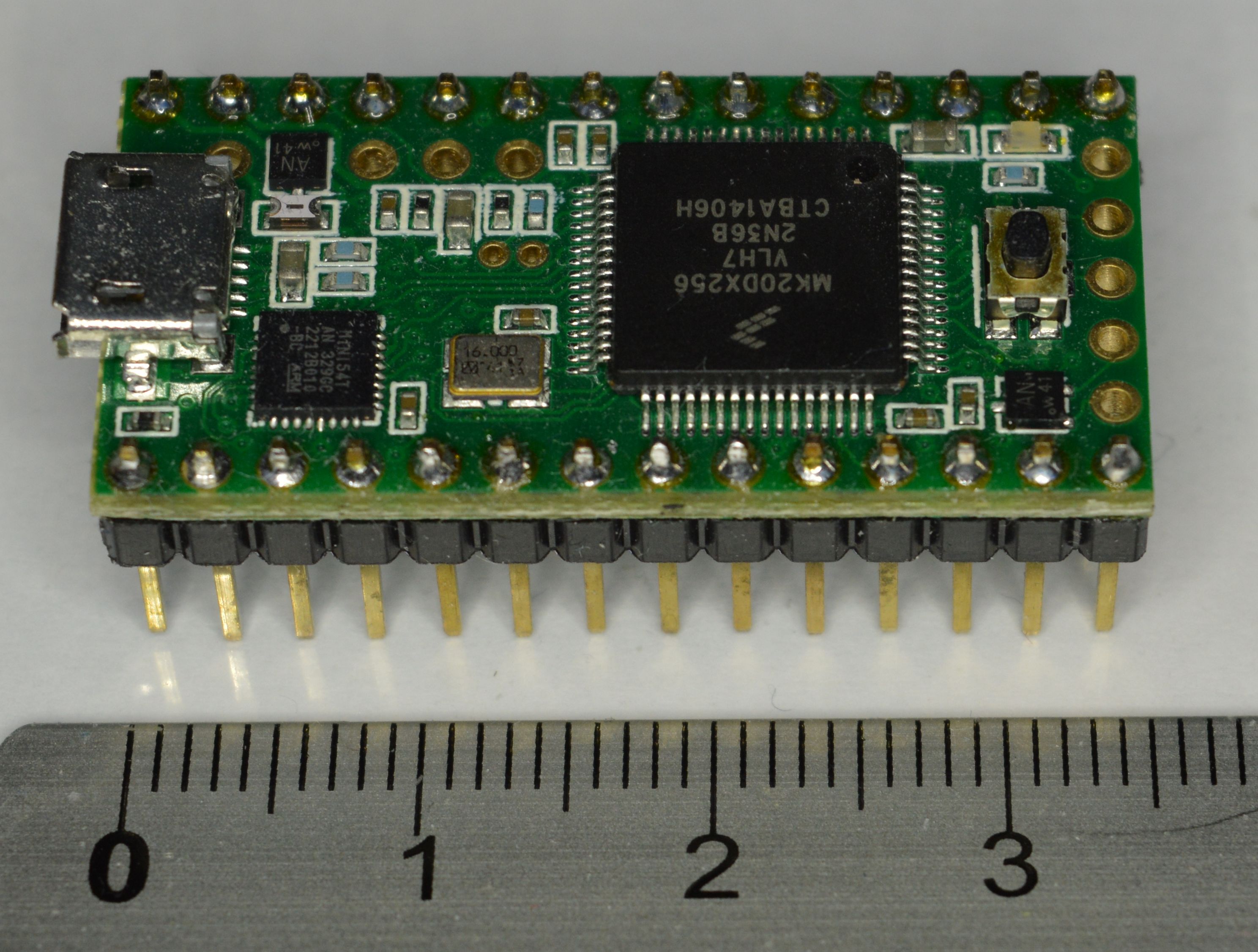
- 34 Digital I/O (3.3V but 5V tolerant)
- 21 analog inputs
- 12 PWM
- SPI, I2C, CAN bus
- ARM DSP extension
The foot print of the board allows it to be easily added to a breadboard.
The Teensy 3.1 board is also supplied with it’s own libraries in the form of Teensyduino. This is an add-on for the Arduino IDE and is compatible with many of the Arduino libraries. The Arduino compatible libraries provide the ability to work with the LED matrix and the addressable LEDs mentioned above as well as a wide variety of other devices.
Software
As I have stated earlier, I am not really a fan of the Arduino IDE. Do not misinterpret me, it represents a great piece of work, however the amount of time and money Microsoft have poured into Visual Studio over the years means that Visual Studio really does take some beating. This is where Visual Micro comes in.
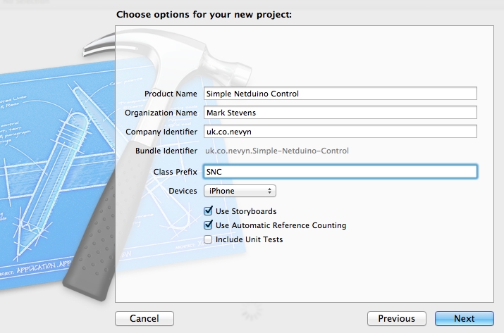
Visual Micro is a Visual Studio 2008-2013 add-in which allows the development of Arduino sketches within the Visual Studio framework. This gives you all the power of Visual Studio (code refactoring etc.) while still allowing the development of Arduino sketches. The add-in is free until the end of 2014 with the option to purchase the debugger support for a nominal fee.
The add-in supports a good number of boards out of the box including the Teensy 3.1.
Setup is simple and the documentation is really good. There are a few additional steps for the Teensy 3.1 but this is cover in the Tips for Teensy page.
Once configured it was a simple task to create a new Teensy 3.1 project using the Neopixel sketch template. A little code reformatting gives the following code:
#include <Adafruit_NeoPixel.h>

//
//	Parameter 1 = number of pixels in strip
//	Parameter 2 = pin number (most are valid)
//	Parameter 3 = pixel type flags, add together as needed:
//		NEO_RGB     Pixels are wired for RGB bitstream
//		NEO_GRB     Pixels are wired for GRB bitstream
//		NEO_KHZ400  400 KHz bitstream (e.g. FLORA pixels)
//		NEO_KHZ800  800 KHz bitstream (e.g. High Density LED strip)
//
Adafruit_NeoPixel strip = Adafruit_NeoPixel(60, 6, NEO_RGB + NEO_KHZ800);

//
//	Input a value 0 to 255 to get a color value.
//	The colours are a transition r - g - b - back to r.
//
uint32_t Wheel(byte WheelPos)
{
	if (WheelPos < 85)
	{
		return strip.Color(WheelPos * 3, 255 - WheelPos * 3, 0);
	}
	else if (WheelPos < 170)
	{
		WheelPos -= 85;
		return strip.Color(255 - WheelPos * 3, 0, WheelPos * 3);
	}
	else
	{
		WheelPos -= 170;
		return strip.Color(0, WheelPos * 3, 255 - WheelPos * 3);
	}
}

//
//	Fill the dots one after the other with a colour
//
void colorWipe(uint32_t c, uint8_t wait)
{
	for (uint16_t i = 0; i < strip.numPixels(); i++)
	{
		strip.setPixelColor(i, c);
		strip.show();
		delay(wait);
	}
}

//
//  Set all LEDs to the same colour.
//
void rainbow(uint8_t wait)
{
	uint16_t i, j;

	for (j = 0; j < 256; j++)
	{
		for (i = 0; i < strip.numPixels(); i++)
		{
			strip.setPixelColor(i, Wheel((i + j) & 255));
		}
		strip.show();
		delay(wait);
	}
}

//
//	Slightly different, this makes the rainbow equally distributed throughout
//
void rainbowCycle(uint8_t wait)
{
	uint16_t i, j;

	for (j = 0; j < 256 * 5; j++)
	{ // 5 cycles of all colors on wheel
		for (i = 0; i < strip.numPixels(); i++)
		{
			strip.setPixelColor(i, Wheel(((i * 256 / strip.numPixels()) + j) & 255));
		}
		strip.show();
		delay(wait);
	}
}

//
//	Executed once at startup to set up the board.
//
void setup()
{
	strip.begin();
	strip.show(); // Initialize all pixels to 'off'
}

//
//	The actual main program loop.
//
void loop()
{
	rainbow(20);
	rainbowCycle(20);
}
This code creates an Adafruit_NeoPixel object with the pixels connected to pin 6 of the Teensy 3.1.
Connecting some LEDs top the Teensy and uploading the above code results in the following:
Modifying the code to add a counter will allow testing of the debugging features. The loop code is changed to have a counter variable to test the conditional breakpoint feature:
int count = 0;

//
//	The actual main program loop.
//
void loop()
{
	count++;
	digitalWrite(LED_PIN, HIGH);
	delay(500);
	digitalWrite(LED_PIN, LOW);
	delay(500);
	// Some example procedures showing how to display to the pixels:
	rainbow(20);
	rainbowCycle(20);
}
Adding a breakpoint after the counter increment and making the breakpoint conditional results in the following display:

Sample Code With Breakpoint
Nothing too strange here, pretty much standard for Visual Studio. The breakpoint window shows the breakpoint and the condition:
Debugger Breakpoint Window
Running the code brings up the debugger expression window:
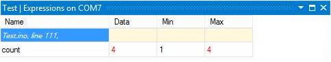
Debugger Expression Window
The one thing which experienced users of Visual Studio will find unfamiliar is the way in which single stepping works. Unlike say Win32 development where single stepping takes you to the next line of code and then waits, with Visual Micro, single stepping runs the code to the next breakpoint.
Conclusion
Visual Studio is without doubt one of the best software development environments available. The addition of Visual Micro brings the power of Visual Studio to the Arduino world. Whilst the debugging features (single stepping) may a little unfamiliar to Visual Studio users they are not so strange as to be unusable.
Both the Teensy 3.1 and Visual Micro are a welcome addition to the development tools and it is highly likely that they will appear in future posts.